How To Install Native Swing POS on Windows
This guide is a work in progress.
Introduction
The purpose of this document is to describe the necessary configuration needed to install the Enactor Native POS application.
Overview
This guide will cover the installation of the Enactor Native POS application on Windows.
The Estate Manager must be installed and configured before you install the Native POS application. Additionally, the following entities should be configured prior to installation: device, location, and POS terminal. Configuration steps for device, location, and POS terminal settings are described in the separate document: How To Configure a New Store.
Prerequisites
To complete the installation, you need:
-
Minimum 10GB of free disk space.
-
Database server with user and database schema created.
-
Estate Manager on version 2.7.1529 or greater.
-
The following configuration present in the Estate Manager:
-
Option set - NATIVE_POS_CONFIG_OPTIONS
-
User - BROADCAST_USER
-
Predefined broadcasts - NATIVE_POS_PDB
-
Process details - PingExtension
-
For Automatic limited broadcast
-
LimitedBroadcastExtension
-
ExportAndBroadcastFilteredData
-
TargetBroadcastDataBroadcastProcessor
-
-
-
Pos Terminal Template - REACT_RETAIL_REDUCED_POS_TEMPLATE
-
-
Network connectivity to the Estate Manager.
-
Network connectivity to the Store Server (v2.7.1529 or greater), if applicable.
*contact your Enactor CSM to receive any of these.
If the Embedded PDC is used, you will also need the following payment configuration:
-
Device (for the PDC)
-
Payment Device (for the PED)
-
Payment Device Host (for the PDC)
-
EFT Merchant ID (for the location)
-
EFT Terminal ID (for the PDC)
Deployment Models
The Native POS configuration will depend on the deployment model. Specifically, will the store server be deployed or will the Native POS connect directly to the Estate Manager.
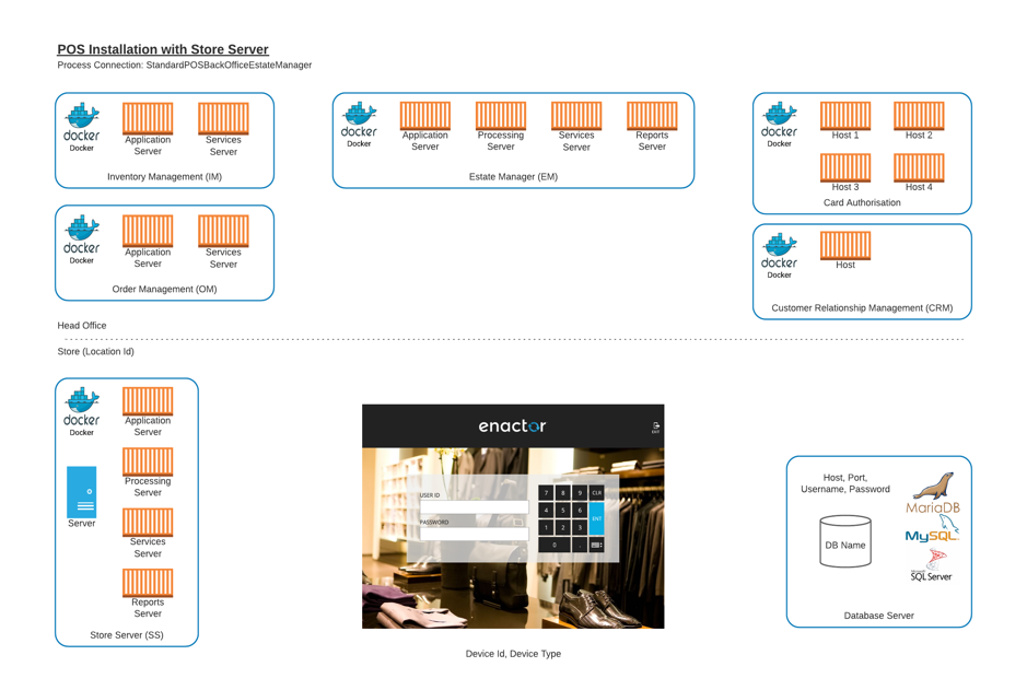
With Store Server
When a store server is deployed for a location, the Native POS will need additional information about the store server hostname for each of the component servers - application, processing, services, and reports.
The process connection will be StandardPosBackOfficeEstateManager.
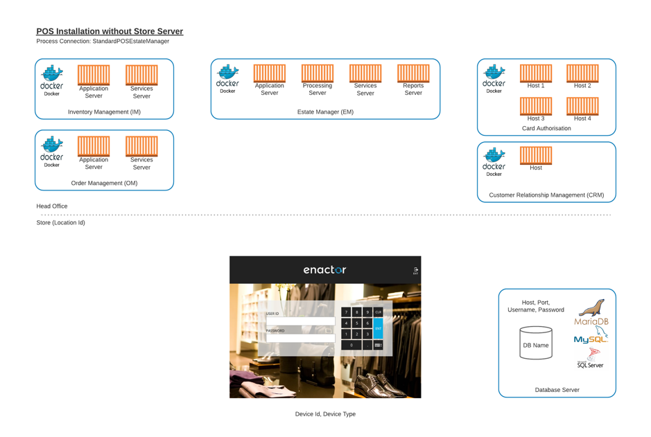
Without Store Server
When the store server is not deployed for a location, the Native POS will connect to the Estate Manager for the component servers - application, processing, services, and reports. Use the Estate Manager hostnames for the store server component server hostnames.
The process connection will be StandardPosEstateManager.
Pre-Installation
Prior to commencing the installation, you should have a database server and a schema created. Installation steps for MariaDB are described in a separate document: How To Guide MariaDB Server Install Instructions for Windows.
There are two files used to install the POS application:
-
EnactorNativePOS-x.x.x-example.ini - a file with all configuration data for the Native POS installer; this file will be copied to installer.ini and can be modified with specific values prior to running the msi installer.
-
EnactorNativePOS-x.x.x.msi - the Windows installer for the Native POS with version x.x.x.
Create the installer.ini file
The installer will look for a configuration file in the same directory: installer.ini.
To create the installer.ini file, copy the EnactorNativePOS-x.x.x-example.ini and rename as installer.ini.
Edit the installer.ini file
The base configuration file for the Native POS application is created by the installer using the data in the installer.ini file. It is essential to set the values correctly prior to install so that future updates of the application using the Application Updater will have the correct values if the Native POS is updated.
The installer.ini file is a Windows INI file with key and value pairs identified by key=value. The file contains the core properties that are required to install the Enactor Native POS application. We will replace values in the file as needed for the POS application.
Required Modifications
The installer.ini file must be modified to meet the requirements of the database connection. The example file that is provided with the installer contains all the core values that need to be configured. Use the values from the worksheet unless otherwise instructed.
Installation Worksheet
The following information can be used to help populate the installer.ini file.
The 'Example Value' column below contains sample values. These values will vary depending on the environment configuration and database used.
Database Server
The following table contains the required configuration to enable the Native POS to connect to the database.
| Property .ini file | Example Value | enactor.xml value | Description |
|---|---|---|---|
| DATABASE_DRIVER | com.mysql.jdbc.Driver | driverName | The driver will vary depending on the database server that is used. When MariaDB is installed, com.mysql.jdbc.Driver is specified. |
| DATABASE_IDENTIFIER | MYSQL | QueryTranslator.DatabaseIdentifier | The database server also has an identifier that is used by the application to make the connection to the database. When MariaDB is used, MYSQL is used as the identifier. |
| DATABASE_PASSWORD | En4ct0rSt0re | encryptedPassword | Database Password that the Native POS will use. |
| DATABASE_SCHEMA | enactorpos | Common.DatabaseSchema | Database Schema name that the Native POS will connect to. |
| DATABASE_URL | jdbc:mysql://localhost:3306/enactorpos?serverTimezone=UTC&defaultFetchSize=1000&useCursorFetch=true&useLegacyDatetimeCode=false&serverTimezone=Europe%2FLondon&useUnicode=true&characterEncoding=UTF-8 | serverName | Database Server URL that the Native POS will connect to. |
| DATABASE_USERNAME | enactorpos | username | Database Username that the Native POS will use. |
The ports specified above are Enactor's default values - if alternative port numbers are used, they should be updated accordingly.
Optional Database Installation
This section can be skipped if MariaDB is already installed.
The following table contains the configuration required to perform a MariaDB server installation alongside the Native POS installation.
| Property .ini file | Example Value | Description |
|---|---|---|
| ENABLE_DATABASE_INSTALLATION | true | The flag to instruct the installer that a headless installation of MariaDB should be carried out alongside the Native POS installation. |
| DATABASE_INSTALL_PATH | ${installer.databaseInstallPath} | The path where the database will be installed. If the default value is used, the installation path will be: {enactorRoot}\shared\mariadb |
| DATABASE_PORT | 3306 | The database port. |
| DATABASE_DOWNLOAD_URL | https://downloads.mariadb.com/MariaDB/mariadb-10.11.3/winx64-packages/mariadb-10.11.3-winx64.zip | The web address to download the version of MariaDB server to install. |
The ports specified above are Enactor's default values - if alternative port numbers are used, they should be updated accordingly.
Configuration Steps
The following steps outline how to configure the Option Set, Client Configuration Set, Device and POS Terminal to enable serial registration for a Native POS device.
Attribute / Option Sets
Option Sets are typically used to create user-configurable data entry fields, for which value options may also be supplied. The option set described in this step contains all the necessary properties used by the Enactor Native POS application.
The Attribute / Option Set maintenance application can be accessed
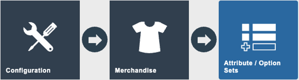
Navigate to:
Configuration > Merchandise > Attribute / Option Sets
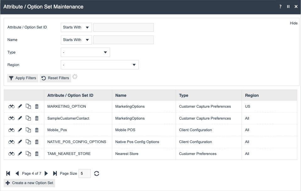
Find and press View on the NATIVE_POS_CONFIG_OPTIONS entry to view its contents. This Option Set is included in the Standard Configuration 2 bundle.

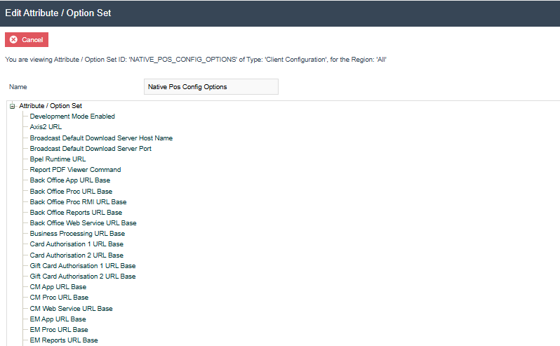
This entry is of type 'Client Configuration' for the Region 'All' and is already populated with core, additional, and payment configuration options.
Core Configuration
| Name | ID |
|---|---|
| Development Mode Enabled | Common.DevelopmentMode |
| Axis2 URL | axis2.url |
| Broadcast Default Download Server Host Name | Broadcast.DefaultDownloadServerHostName |
| Broadcast Default Download Server Port | Broadcast.DefaultDownloadServerPort |
| Bpel Runtime URL | Bpel.RuntimeURL |
| Report PDF Viewer Command | Report.PDFViewerCommand |
| Back Office App URL Base | Server.BOApp.URL.Base |
| Back Office Proc URL Base | Server.BOProc.URL.Base |
| Back Office Proc RMI URL Base | Server.BOProcRMI.URL.Base |
| Back Office Reports URL Base | Server.BOReports.URL.Base |
| Back Office Web Service URL Base | Server.BOWS.URL.Base |
| Business Processing URL Base | Server.BP.URL.Base |
| Card Authorisation 1 URL Base | Server.CardAuth1.URL.Base |
| Card Authorisation 2 URL Base | Server.CardAuth2.URL.Base |
| Gift Card Authorisation 1 URL Base | Server.GiftCardAuth1.URL.Base |
| Gift Card Authorisation 2 URL Base | Server.GiftCardAuth2.URL.Base |
| CM App URL Base | Server.CMApp.URL.Base |
| CM Proc URL Base | Server.CMProc.URL.Base |
| CM Web Service URL Base | Server.CMWS.URL.Base |
| EM App URL Base | Server.EMApp.URL.Base |
| EM Proc URL Base | Server.EMProc.URL.Base |
| EM Reports URL Base | Server.EMReports.URL.Base |
| EM Web Service URL Base | Server.EMWS.URL.Base |
| PM URL Base | Server.PM.URL.Base |
| IM Proc URL Base | Server.IMProc.URL.Base |
| IM WS URL Base | Server.IMWS.URL.Base |
| OM WS URL Base | Server.OMWS.URL.Base |
| RRS URL Base | Server.RRS.URL.Base |
| Process Connections Definition ID | ProcessConnections.DefinitionId |
| React Pos Content URL | ReactPos.contentUrl |
| Synchronous Retail Queue Connector Module | ServiceModules.SynchronousRetailQueueConnectorModule |
| Synchronous Scheduled Job Feeder Module | ServiceModules.SynchronousScheduledJobFeederModule |
Additional Configuration
| Name | ID |
|---|---|
| Automatic Purging | Module.AutomaticPurging.Enabled |
| Predefined Broadcast ID for Automatic Broadcast | Broadcast.Predefined.BroadcastID |
| Broadcast Changes Period | Broadcast.ChangesPeriod |
| Enable Run Services | Common.Manage.EnableRunServices |
| Background Services Supported | BackgroundServices.Supported |
| Keep Screen On | Common.KeepScreenOn |
| Customer Collections Module | Modules.CustomerCollectionsModule |
| Order Module | Modules.OrderModule |
| Time Attendance Module | Modules.TimeAttendanceModule |
| Re-Register Password | Application.Settings.Password |
Payments Configuration
| Name | ID |
|---|---|
| Embedded PDC | Pdc.EmbeddedPdcEnabled |
| PDC Company Name | Pdc.CompanyName |
| PDC Datasource Name | Pdc.DatasourceName |
| PDC Database Location | Pdc.DatabaseLocation |
| Payment Portal Host | Server.PP.Host |
| PDC Primary TMS URL | Pdc.PrimaryTmsUrl |
| PDC Secondary TDMS URL | Pdc.SecondaryTmsUrl |
| PDC Key ID | Pdc.KeyId |
| PDC Public Key | Pdc.PublicKey |
Press Cancel as no configuration changes are needed here.
Adding Additional Options to Option Sets
The NATIVE_POS_CONFIG_OPTIONS Option Set, referenced in this document, provides a baseline of common properties for configuration.
Please note that this set is not exhaustive; it does not contain every possible property available in the enactor.xml file. If your implementation requires a property that is not already listed, you must add it.
The following steps will guide you through adding any new properties to the Option Set.
Edit the Option Set.

Select Add.
Select the appropriate option type (such as 'Add Boolean Option' for true/false or 'Add Text Option' for text) that matches the kind of data this property will store.
Fill in the Option ID with the exact property ID (e.g., Broadcast.Predefined.BroadcastID) and then enter a friendly Name (e.g., 'Predefined Broadcast ID') that will be used as the display label.
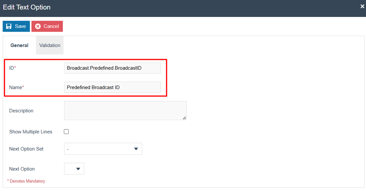
Press Save
Client Configuration Set
To enable the use of the previously viewed Option Set, a Client Configuration Set must be configured with the appropriate values for each property. These values will be used during the serial registration step to generate the enactor.xml file used by the application.
The Client Configuration Set maintenance application can be accessed through:
Navigate to:
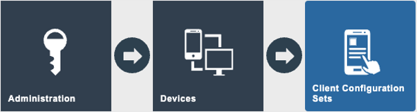
Administration > Devices > Client Configuration Sets
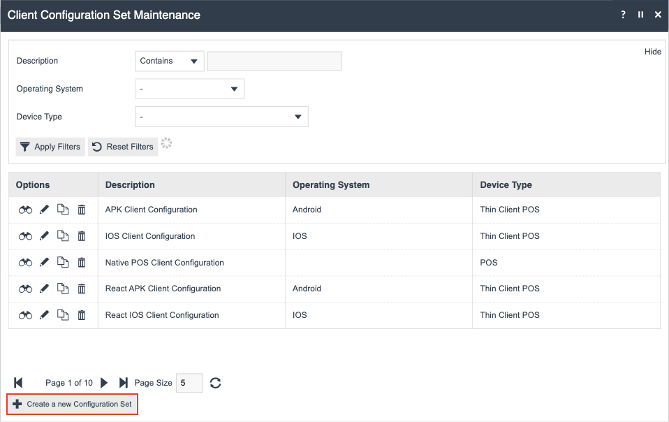
Press the Create a new Configuration Set button.
General tab
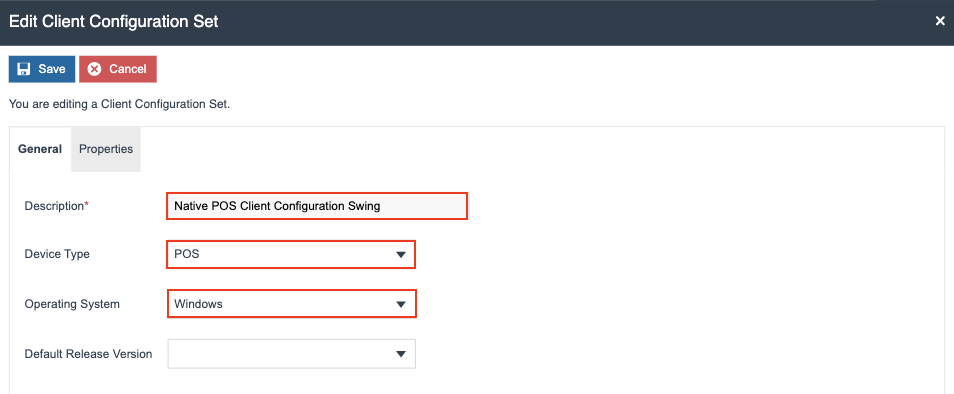
Configure these properties as follow:
| Name | Value | Description |
|---|---|---|
| Description | Native POS Client Configuration Swing | Provide a name for the client configuration set. |
| Device Type | POS | Select the device type. |
| Operating System | Windows | Select the operating system. |
Select the Properties tab.
Properties tab
Select Native Pos Config Options from the Property Set drop down list.
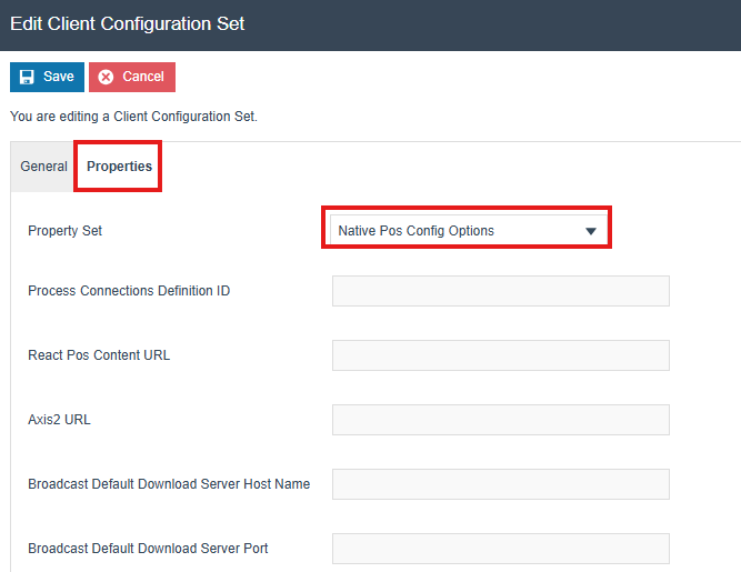
Values for each property can be entered here. These values will be used to generate the enactor.xml file during the registration process using a serial number.
All available properties are described below, along with sample values. The properties are categorized into Core, Additional, and Payments groups.
Core Configuration
Configure these properties as follow, replacing xx.xxx.xx.xxx with your Estate Manager Ip address:
| Name | Value | Description |
|---|---|---|
| Axis2 URL | http://xx.xxx.xx.xxx:39833/axis2 | Set the axis 2 URL. |
| Broadcast Default Download Server Host Name | xx.xxx.xx.xxx | Set the broadcast default download server host name. |
| Broadcast Default Download Server Port | 39832 | Set the broadcast default download server port. |
| Bpel Runtime URL | http://xx.xxx.xx.xxx:39832/WebCore | Set the bpel runtime URL. |
| Report PDF Viewer Command | ||
| Back Office App URL Base | http://xx.xxx.xx.xxx:39848 | Set the back office app URL. |
| Back Office Proc URL Base | http://xx.xxx.xx.xxx:39848 | Set the back office proc URL. |
| Back Office Proc RMI URL Base | http://xx.xxx.xx.xxx:39848 | Set the back office proc RMI URL. |
| Back Office Reports URL Base | http://xx.xxx.xx.xxx:39848 | Set the back office reports URL. |
| Back Office Web Service URL Base | http://xx.xxx.xx.xxx:39848 | Set the back office web service URL. |
| Business Processing URL Base | http://xx.xxx.xx.xxx:39832 | Set the business processing URL. |
| Card Authorisation 1 URL Base | http://xx.xxx.xx.xxx:39856 | Set the first card auth server URL. |
| Card Authorisation 2 URL Base | http://xx.xxx.xx.xxx:39856 | Set the second card auth server URL. |
| Gift Card Authorisation 1 URL Base | http://xx.xxx.xx.xxx:39856 | Set the first gift card auth server URL. |
| Gift Card Authorisation 2 URL Base | http://xx.xxx.xx.xxx:39856 | Set the second gift card auth server URL |
| CM App URL Base | http://xx.xxx.xx.xxx:39830 | Set the CM app URL. |
| CM Proc URL Base | http://xx.xxx.xx.xxx:39832 | Set the CM proc URL. |
| CM Web Service URL Base | http://xx.xxx.xx.xxx:39833 | Set the CM web service URL. |
| EM App URL Base | http://xx.xxx.xx.xxx:39830 | Set the EM app URL. |
| EM Proc URL Base | http://xx.xxx.xx.xxx:39832 | Set the EM proc URL. |
| EM Reports URL Base | http://xx.xxx.xx.xxx:39831 | Set the EM reports URL. |
| EM Web Service URL Base | http://xx.xxx.xx.xxx:39833 | Set the EM web service URL. |
| PM URL Base | http://xx.xxx.xx.xxx:39833 | Set the PM URL. |
| IM Proc URL Base | http://xx.xxx.xx.xxx:39832 | Set the IM proc URL. |
| IM WS URL Base | http://xx.xxx.xx.xxx:39833 | Set the IM web service URL. |
| OM WS URL Base | http://xx.xxx.xx.xxx:39837 | Set the OM web service URL. |
| RRS URL Base | http://xx.xxx.xx.xxx:39833 | Set the RRS URL. |
| Process Connections Definition ID | StandardPosBackOfficeEstateManager | Set the process connection diagram based on your deployment model: StandardPosEstateManager or StandardPosBackOfficeEstateManager. |
| React Pos Content URL | apps/react-pos-all-app/index.html | Set the UI content URL. |
| Payment Portal Host | Set the payment portal host. | |
| Synchronous Retail Queue Connector Module | Enabled | Enable the Synchronous Retail Queue Connector module. |
| Synchronous Scheduled Job Feeder Module | Enabled | Enable the Synchronous Scheduled Job Feeder module. |
The ports specified above are Enactor's default values - if alternative port numbers are used, they should be updated accordingly.
Additional Configuration
Configure these properties as follow:
| Name | Value | Description |
|---|---|---|
| Automatic Purging | Enabled | Toggle automatic purging, which contain rules to purge certain entities and files from tables and directories. This is independent of your location purging configuration. |
| Broadcast Predefined Broadcast ID | NATIVE_POS_PDB | Predefined Broadcast ID used to automatically request data from the Estate Manager during the application's first startup. |
| Broadcast Changes Period | 5 | Specify the number of years to filter the data sent by the automatic broadcast, ensuring only data from the last 'x' years is included. |
| Keep Screen On | Disabled | Prevent the device from sleeping. Not required on Swing. |
| Customer Collections Module | Enabled | Enable or disable the Customer Collections Module. |
| Order Module | Enabled | Enable or disable the Order Module. |
| Time Attendance Module | Enabled | Enable or disable the Time Attendance Module. |
| Re-Register Password | 12345 | Expected PIN to allow Re-Registering the device via the Context Menu. |
| Enable Run Services | Enabled | Enable the background services. |
| Background Services Supported | Enabled | Enable the background services. |
Payments Configuration
Configure these properties as follow, replacing xx.xxx.xx.xxx with your TMS IP address:
| Name | Value | Description |
|---|---|---|
| Embedded PDC | Enabled | Enable or disable the embedded PDC. This is a separate application that runs in conjunction with the Native POS. |
| PDC Company Name | Enactor Ltd | The company name. |
| PDC Datasource Name | enactorpdc | The data source name of the PDC. |
| PDC Database Location | C:\Enactor\pos\Databases\pdc\enactorpdc | The path to the PDC database location. |
| PDC Primary TMS URL | http://xx.xxx.xx.xxx/PaymentDevicemanagementService | IP address of the primary TMS. |
| PDC Secondary TMS URL | http://xx.xxx.xx.xxx/PaymentDevicemanagementService | IP address of the secondary TMS. |
| PDC Key ID | Set the PDC Key ID | |
| PDC Public Key | Set the PDC Public Key ID |
Press Save to save the configuration.
Devices
The device entity of a Native POS requires additional configuration to enable serial number registration. This step covers selecting the appropriate Configuration Set and the necessary values to generate a serial number.
The Devices maintenance application can be accessed through:
Navigate to:
Administration > Devices > Devices

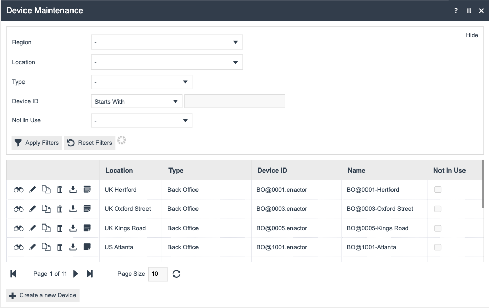
If a Device record for the Native POS has already been created, Edit/ Copy it. Alternatively, a new Device record can be created.
For more configurations on the Devices and POS Terminals refer: How To Configure a New Store.
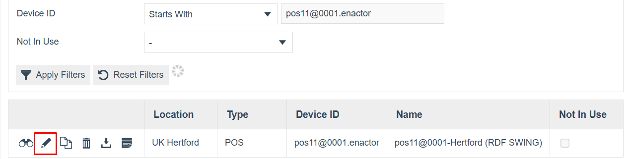
Select the Registration tab.
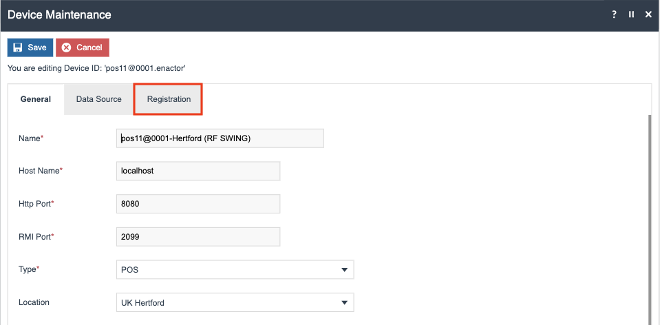
This is the tab where details for the serial registration are entered.
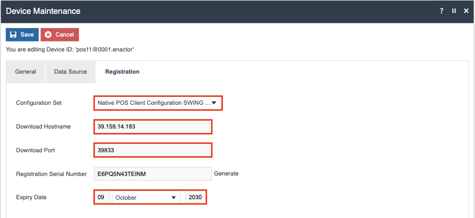
Configure these properties as follow, replacing xx.xxx.xx.xxx with your Estate Manager IP address:
| Name | Value | Description |
|---|---|---|
| Configuration Set | Native POS Client Configuration Swing | Select the Client Configuration Set to use. |
| Download Hostname | xx.xxx.xx.xxx | IP address of the Estate Manager to download the configuration settings. |
| Download Port | 39833 | EM Server port. |
| Expiry Date | 09 October 2030 | Date of expiry of the serial number. |
Once Configured, Press Save
POS Terminals
The POS Terminal entity for a Native POS requires additional configuration to properly utilize the POS Terminal Template. This section details the necessary steps to both update the POS Terminal template and configure the Embedded PDC in POS Terminal.
The POS Terminal maintenance application can be accessed through:
Navigate to:
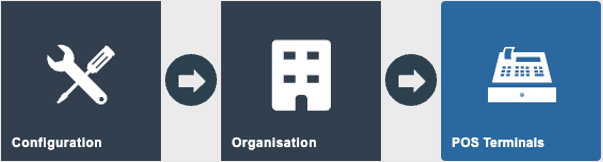
Configuration > Organisation > POS Terminals
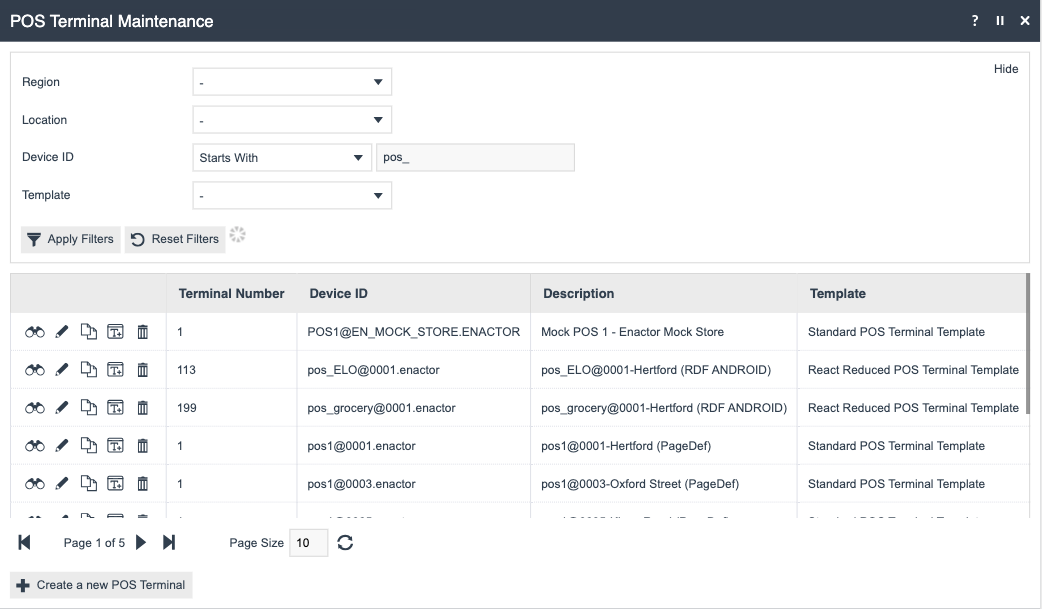
Edit the designated POS Terminal. Navigate to the General main tab and then the Overview sub tab. Change the POS Terminal Template to 'React Reduced POS Terminal Template'.
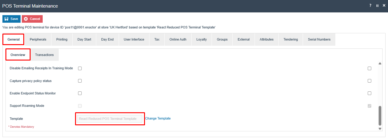
Then, press Save.
The following step only requires if you plan to use the Embedded PDC instead of an external one. The Embedded PDC functions like any standard PDC and is bundled directly with the Native POS application.
Edit the POS Terminal and select the Peripherals tab.
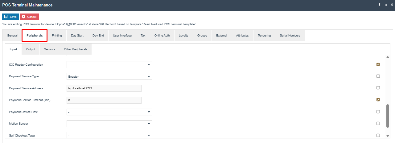
Select the Payment Device Host that the Embedded PDC should use.
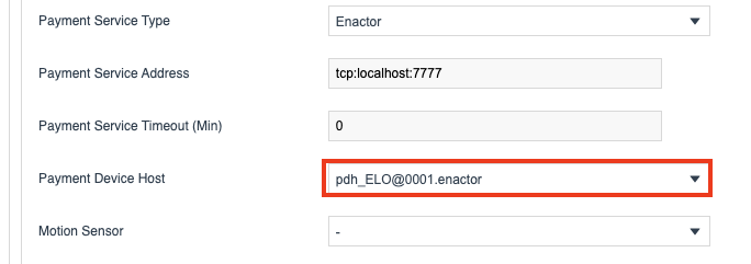
Lastly, press Save.
The Payment Device Host ID added in the POS terminal configuration will override the value given in the Client Configuration Set.
After POS Terminal configurations, go back to the Device Maintenance, edit the device, and select the Registration tab.
Then press the Generate button next to the Registration Serial Number field. This will generate the serial needed to register the Native POS device. The Serial number is dependent only on the Download Hostname and the Download Host port. You have to re-generate the serial number only if these values are modified.
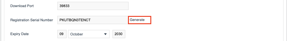
Take note of the serial number to be used during the registration and press Save.
MSI Installation
Running the MSI
Ensure that the provided MSI installer and installer.ini file are located in the same directory. Double click on the MSI file to trigger the installation.
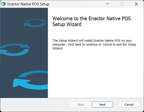
Select Next.
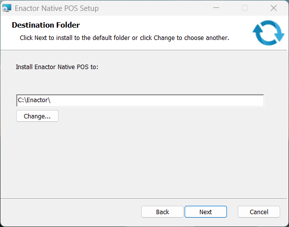
The default installation path is C:\Enactor. This can be changed if desired. Select Next again.
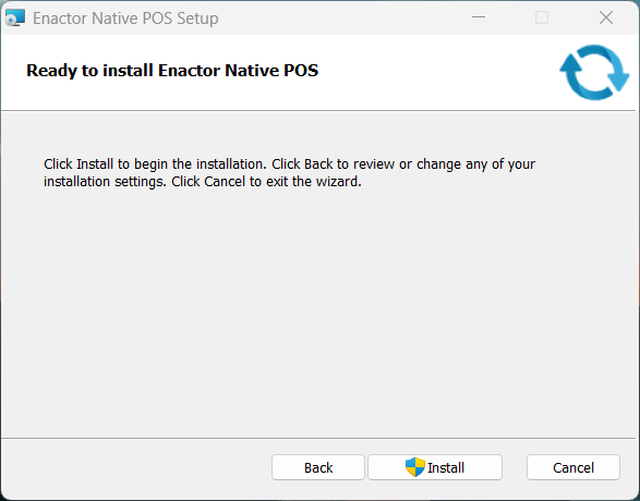
Select Install.
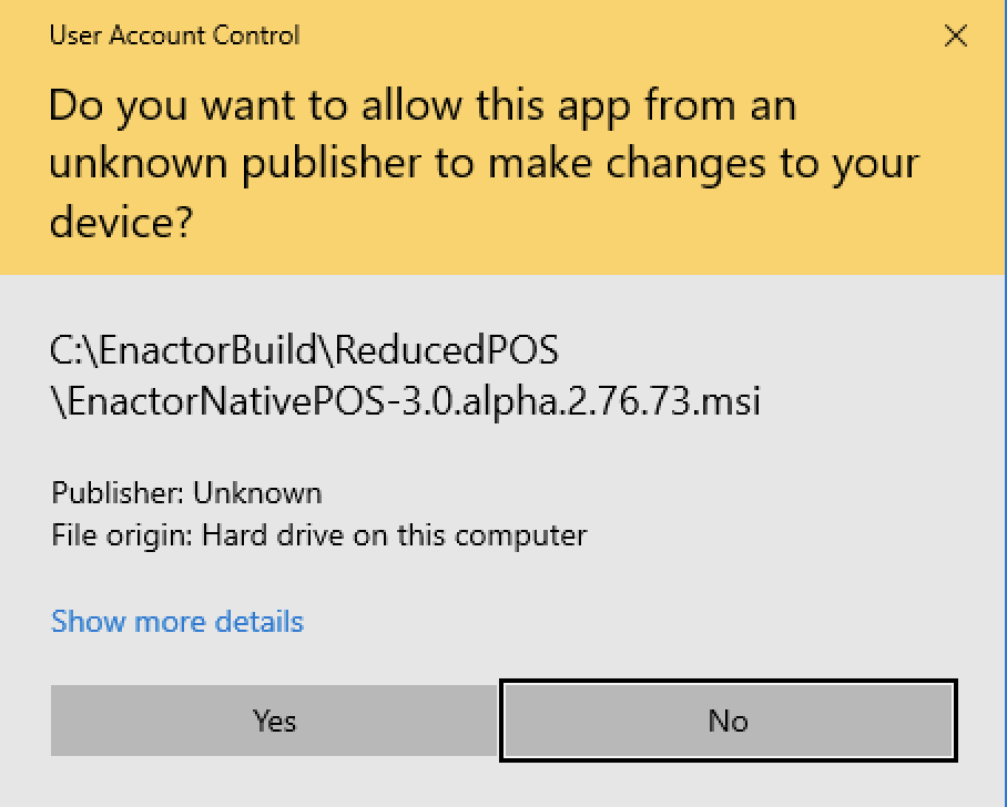
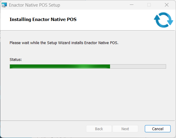
Select Yes. The installation will proceed to completion.
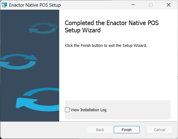
Select Finish and the installation is complete.
The Enactor POS Service Windows service will not start immediately. The service will start after the Device Registration process (described later in this document) is completed.
Native POS Registration
When the Enactor Native POS is launched for the first time, the application initialises without any device-specific configuration, as the download of such data is deferred to the serial number registration step.
Serial Number Registration
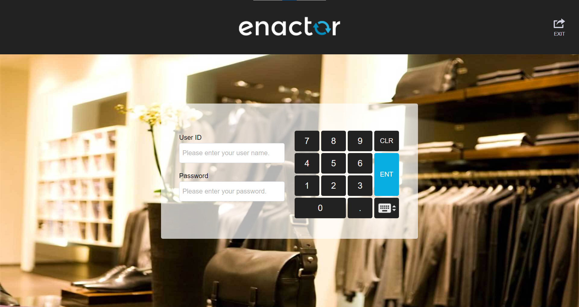
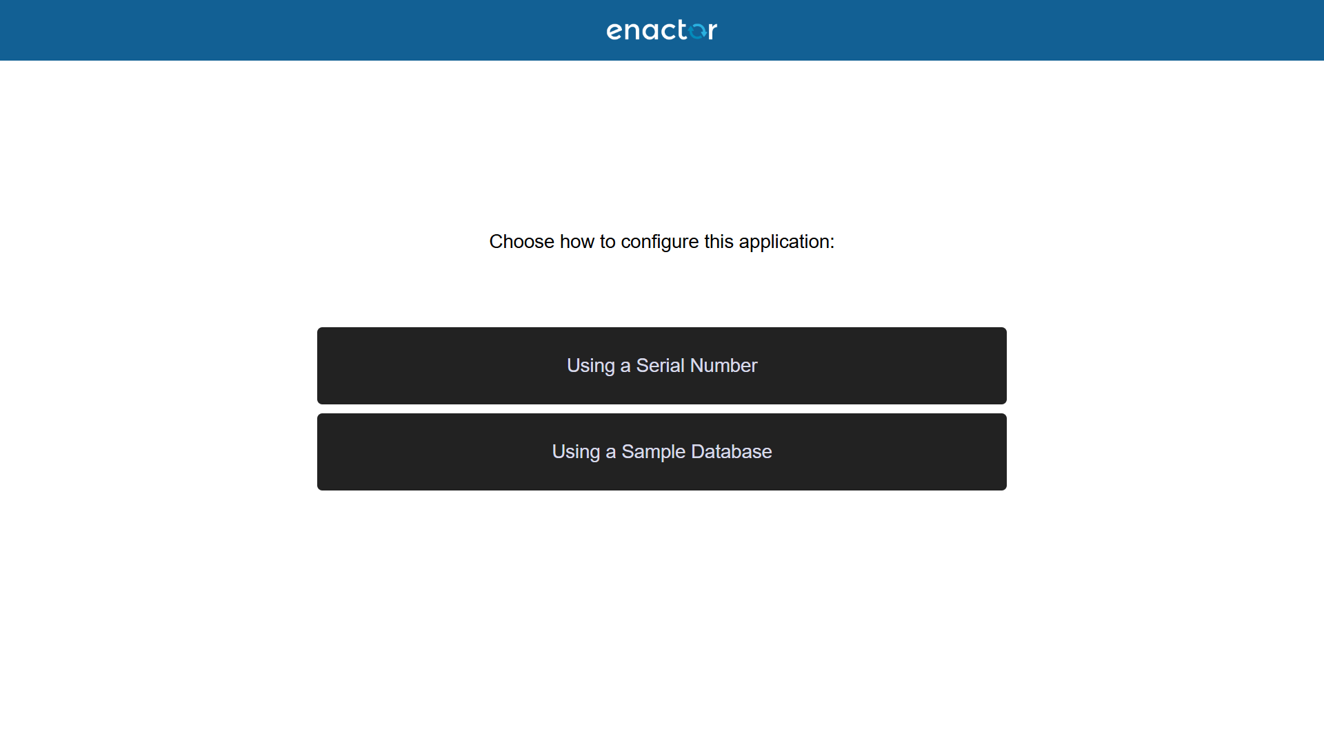
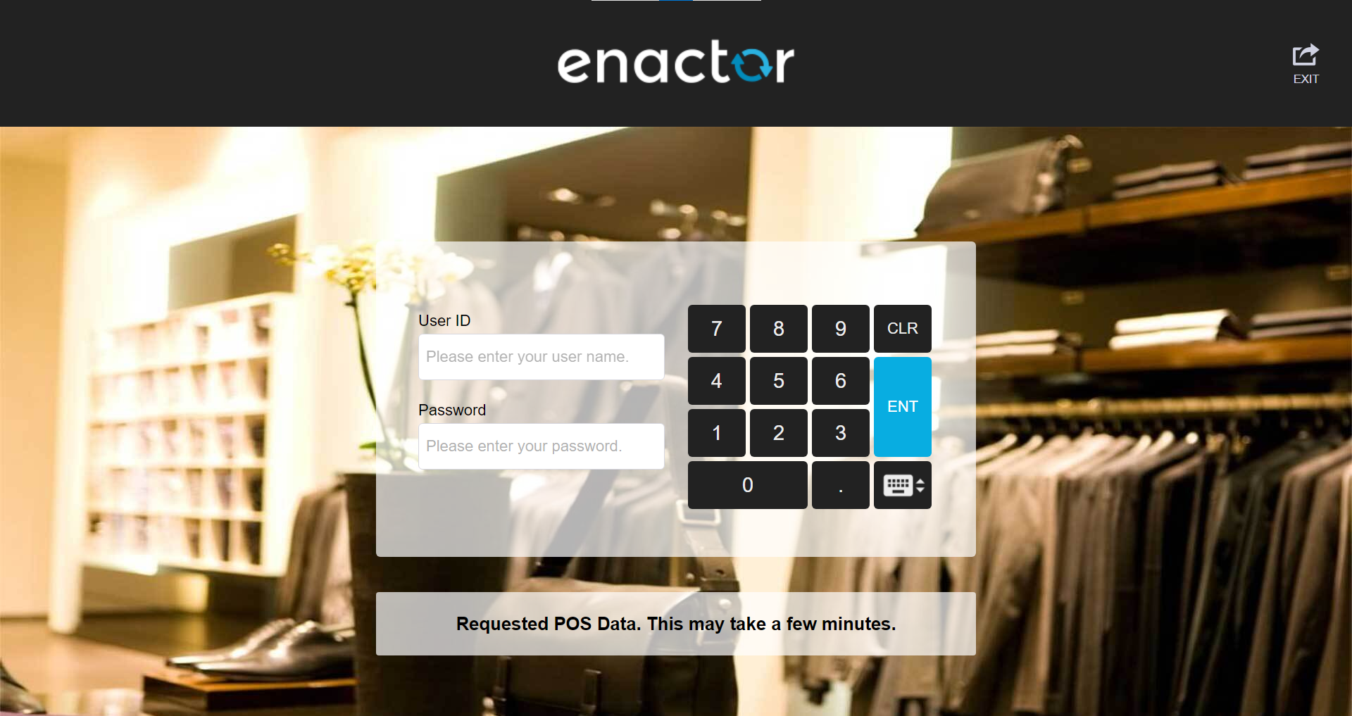
Launch the Enactor Native POS using the desktop shortcut created by the installer. This action creates the database tables and the Data folder. Select the Using a Serial Number option.
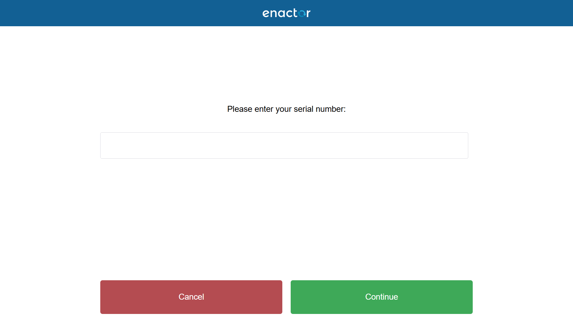
Enter the device's registration serial number, then press Continue.
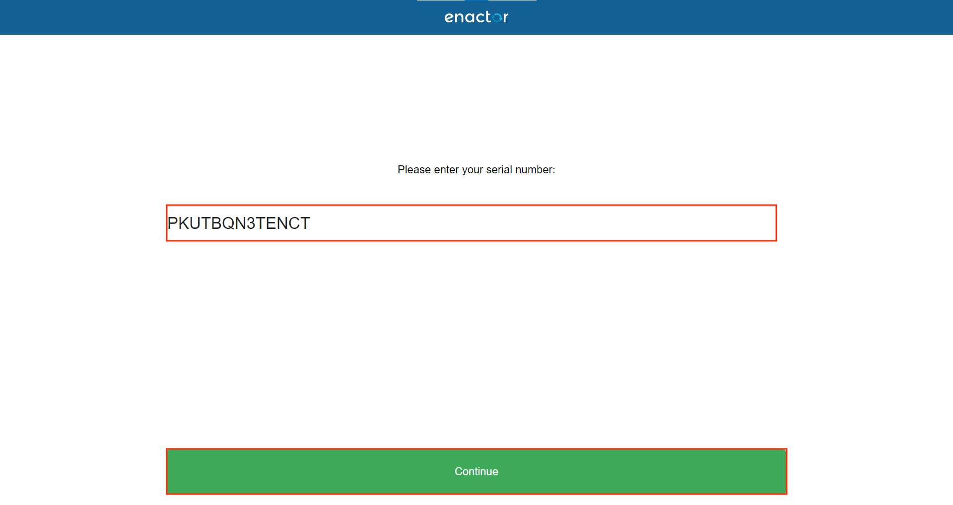
A call is then made to the Estate Manager to identify the POS device being configured.
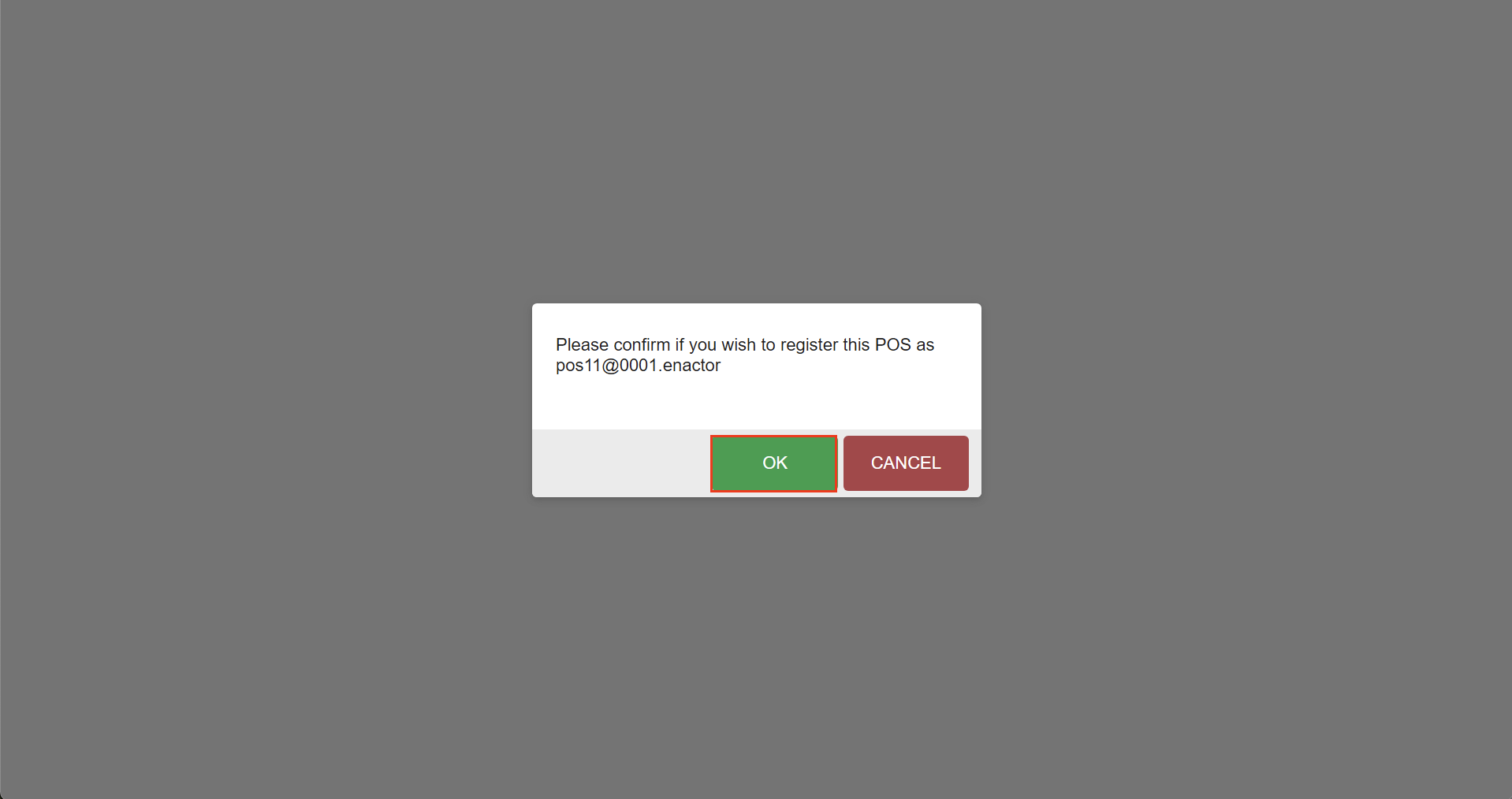
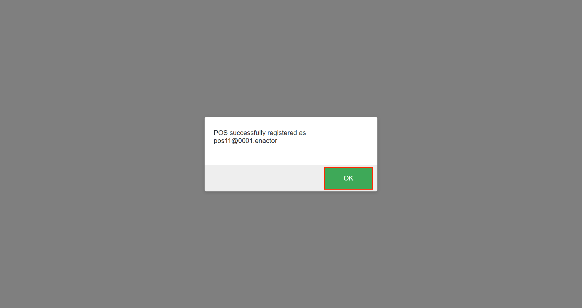
If successful, a pop-up message appears asking for confirmation to register the device.
Press OK to confirm.
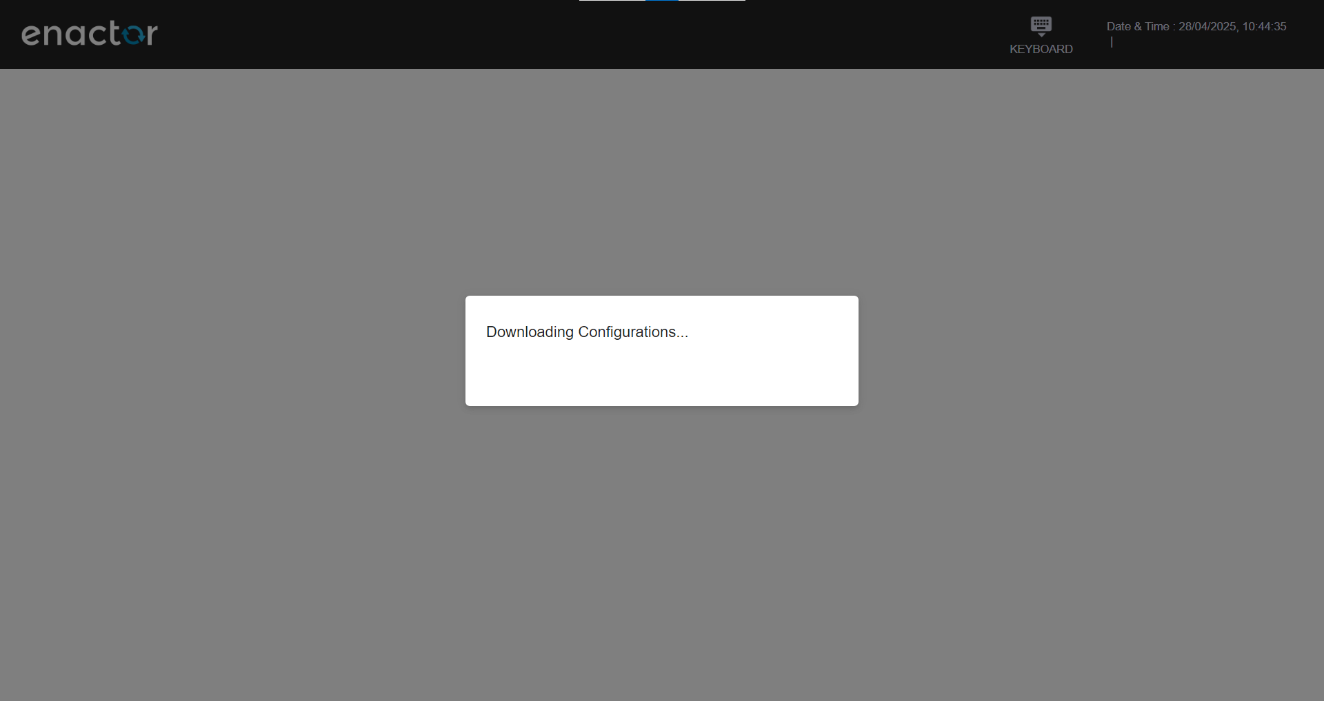
The application then downloads an initial set of configuration data required to identify and initialize the POS terminal, along with the properties and values of its Client Config Set.
The downloaded configuration includes the device, POS terminal, POS terminal template, location, and location template entities.
This step also generates the device-specific enactor.xml file (located in the SettingsCache folder) by merging the base enactor.xml with the data retrieved from the Client Config Set.
Once the download is complete, a message appears confirming the successful registration of the device. Press OK to continue.
This action automatically sends a request to the Estate Manager to download static data using the predefined broadcast NATIVE_POS_PDB by the user BROADCAST_USER.
A series of messages indicate the progress and stages of the broadcast.
The first message reads: 'Requesting POS Data. This may take a few minutes.'

Once the request is acknowledged by the Estate Manager, the message updates to: 'Requested POS Data. This may take a few minutes.'
The broadcast request is then processed, exported, and sent to the POS.
When the POS receives the instructions to download the broadcast .zip file, the toast message updates to: 'Notification received. Downloading and importing data.'

Once the initial broadcast has been successfully imported, a final message appears: 'Data fully received and ready to use.'

The message disappears after a few seconds, and the POS is then ready for use.