How to Extend Connected Process Diagrams
Overview
Process Connection Diagrams (sometimes just called Connection Diagrams or Process Connections) are used to specify how different devices in an Enactor estate talk to each other. This can include:
- Where on the network a particular service is available
- What credentials should be used to access a service
- Any message transformation that might be required to call the service
Enactor will ship with a default connection diagram that will support most "out-of-the-box" installations, however it is frequently necessary to define custom behaviour to suit customer requirements.
What You Will Learn
- How to create Process Connection Diagram extensions
- How to override existing connections
- How to add new connections
Prerequisites
- General understanding of Process Connection Diagrams, including what Queue Connectors are
Instructions
Rather than changing the "built in" diagram Enactor allows you to specify a custom "extension" diagram. When the Enactor application runs it will then use information from the custom extension diagram and that from the built-in diagram together.
This approach allows you to only define the "changes" in your diagram, and not have to worry about standard functionality.
When Enactor is asked to resolve a connection, it will use the following process:
- First resolve the Process Connection Diagram specified by the enactor.xml using the
ProcessConnections.DefinitionIdproperty.
This diagram will be loaded from the database if it is present, otherwise it will be found in the filesystem or the application archives (jar files) - Enactor then checks the database for
ProcessConnectionTypeentries.
These are used to configure extensions. If an extension is specified, Enactor will then load the extension diagram. - Now Enactor has all the diagrams, it will check them for the specified connection.
Enactor will first check all the extension diagrams for the connection. If a connection is found it is returned and the standard diagram is not checked. - If a connection is not found in any extension diagrams, Enactor will then fall-back to looking in the standard diagram.
Supported Behaviours
Examples of the kind of things you can use Process Connection Diagram Extensions to do include:
- Change where a message would be sent
- Change what credential would be used for a specific endpoint
- Add new connections for custom service calls
It is not possible to "disable" parts of the diagram you are extending - for example stopping a message being sent to a queue. However you can "replace" existing routes with your own custom destinations.
Creating a Process Connection Diagram Extension
Process Connection Diagram Extensions are edited using the standard Process Connection Editor.
To create a new extension, first create a new empty XML document using the Eclipse File Wizard:
-
The standard folder for Process Connections is:
src/META-INF/deployments/ProcessConnection. Prepare an empty directory in theTraining - Common Dataproject. -
Right-click on the folder and open the Eclipse File Wizard:
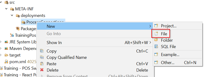
-
Enter a suitable filename for the new diagram and click
Finish. Again, if you are following Enactor conventions use the filename:<CustomerName>Connections.xml: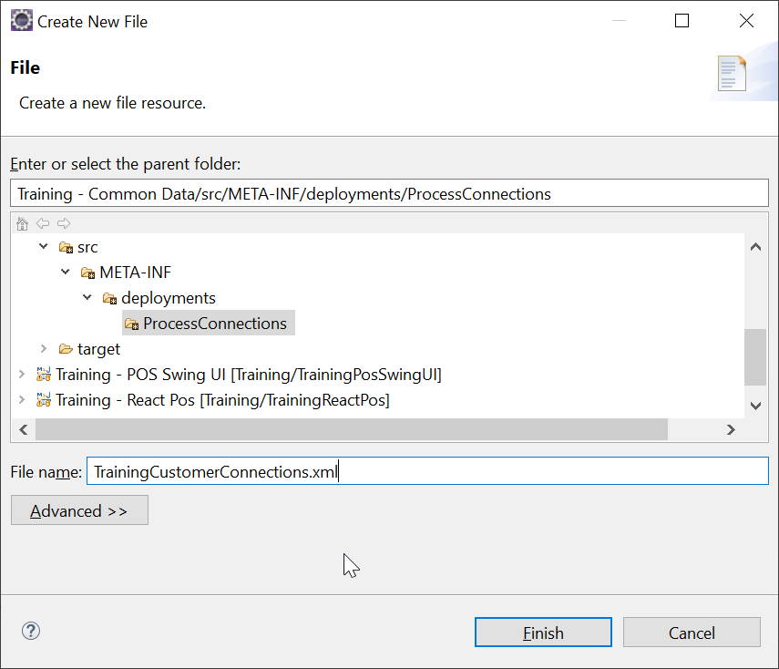
-
Eclipse will open an XML editor. Paste the following content into to create an empty Process Connection Diagram:
<?xml version="1.0" encoding="UTF-8" standalone="yes"?>
<!DOCTYPE xml>
<core:processConnections xmlns:core="http://www.enactor.com/core">
</core:processConnections> -
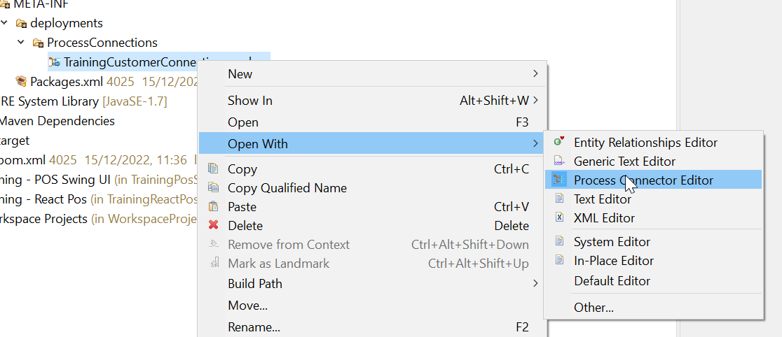
Save the file and you can now right-click and select open the file with the Process Connection Editor:
Registering the Diagram as an Extension
To register your custom diagram as an Extension you will need to record it in your Packages.xml file. The following example file shows a basic extension:
Packages.xml
<?xml version="1.0" encoding="UTF-8" standalone="yes"?>
<core:packages xmlns:core="http://www.enactor.com/core">
    <core:package>
        <core:packageId>Training - Common Data</core:packageId>
        <core:name>Training - Common Data</core:name>
        <core:applicableContexts/>
        <core:deployedStatus>DEPLOYED</core:deployedStatus>
        <core:processConnectionsType>
            <core:description>Connection strategy for Training Customer</core:description>
            <core:name>Training Customer Connections</core:name>
            <core:processConnectionsDefId>TrainingCustomerExtensions</core:processConnectionsDefId>
            <core:extendingConnectedProcessId>StandardPosBackOfficeEstateManager</core:extendingConnectedProcessId>
        </core:processConnectionsType>
        <core:deployment>
            <core:name>Startup Deployment</core:name>
            <core:useLoadThread>true</core:useLoadThread>
            <core:scope>GLOBAL</core:scope>
            <core:deploymentHandler name="Process Connections Def DB Update Handler">
                <core:delay>0</core:delay>
                <core:executionOrder>360</core:executionOrder>
                <core:handlerClassName>com.enactor.core.deployment.common.ProcessConnectionsDefDBUpdateHandler</core:handlerClassName>
                <core:retryCount>0</core:retryCount>
                <core:retryInterval>0</core:retryInterval>
                <core:abortOnFailure>false</core:abortOnFailure>
            </core:deploymentHandler>
        </core:deployment>
        <core:deployment>
            <core:name>Startup Deployment</core:name>
            <core:useLoadThread>true</core:useLoadThread>
            <core:scope>GLOBAL</core:scope>
            <core:deploymentHandler name="Process Connections Type DB Update Handler">
                <core:delay>0</core:delay>
                <core:executionOrder>370</core:executionOrder>
                <core:handlerClassName>com.enactor.core.deployment.common.ProcessConnectionsTypeUpdateHandler</core:handlerClassName>
                <core:retryCount>0</core:retryCount>
                <core:retryInterval>0</core:retryInterval>
                <core:abortOnFailure>false</core:abortOnFailure>
            </core:deploymentHandler>
        </core:deployment>
        <core:extensions/>
        <core:dependencies/>
    </core:package>
</core:packages>
Line 12 tells Enactor this diagram is an extension:
<core:extendingConnectedProcessId>StandardPosBackOfficeEstateManager</core:extendingConnectedProcessId>
in this case we are specifying that the TrainingCustomerExtensions document is an extension of the StandardPosBackOfficeEstateManager document. If we happen to be running in an environment that is not using the StandardPosBackofficeEstateManager document then the extension will not activate.
The deployment sections are necessary only to ensure the connection diagram and its related processConnectionsType is correctly deployed to the database (if you have these deployment handlers in some other Packages.xml you won't need that here too).
Require a particular Device Type
You can optionally restrict where an extension will activate based matching the Device Type using the extensionApplicableHostIds element as shown in the following example:
<core:processConnectionsType>
   <core:description>Connection strategy for Training Customer</core:description>
   <core:name>Training Customer Connections</core:name>
   <core:processConnectionsDefId>TrainingCustomerExtensions</core:processConnectionsDefId>
   <core:extendingConnectedProcessId>StandardPosBackOfficeEstateManager</core:extendingConnectedProcessId>
   <core:extensionApplicableHostIds>
		<core:extensionApplicableHostId>POS</core:extensionApplicableHostId>
		<core:extensionApplicableHostId>MASTER_POS</core:extensionApplicableHostId>
	</core:extensionApplicableHostIds>
</core:processConnectionsType>
If these properties are specified the extension will only be enabled when it is run in an environment which has a Device Type matching one of the types in the list.
If these properties are absent then the extension will be enabled for all Device Types
How to override behaviour using an extension diagram
Now you have an empty document and have registered it as an extension you can start to override behaviour in the standard diagram.
As an example we will configure the POS to send transactions to an additional custom database queue.
To do this we first need to identify the section of the standard diagram we want to override, this is shown below:
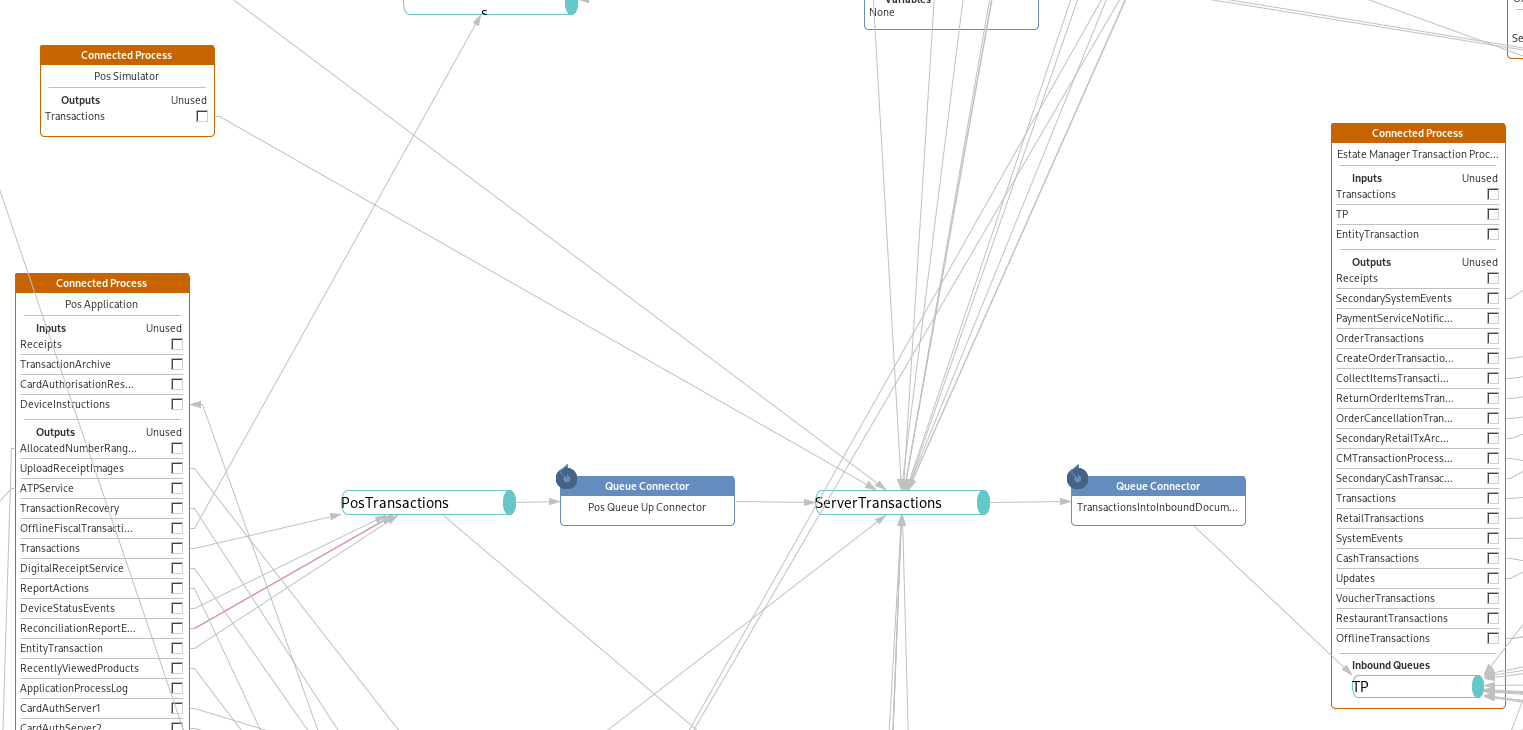
Here you can see the Transactions Output from the Pos Application on the left is configured to write to a PosTransactions queue. The contents of this queue is then forwarded up to the Estate Manager by the Pos Queue Up Connector Queue Connector, which writes it into the ServerTransactions queue.
For us to send the transactions to an additional queue we can reuse the existing PosTransactions queue and configure and our own custom Queue Connector.
-
We first need to tell the application how it should read and write from Queues, this is done by configuring a
Queue Connection Provider. Enactor provides a number of different providers out-of-the box, we will the the standard Database Queue Providers. To set this up show the Eclipse Outline view and, making sure your custom connection diagram is selected, right-click on theQueue Connection Providerssection of the tree:
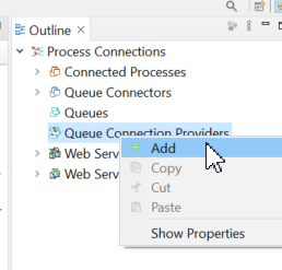
Select theAddoption. -
If you expand the
Queue Connection Providerssection you will now see anUnnamedentry. Select that and you can then configure it using the Properties view in Eclipse: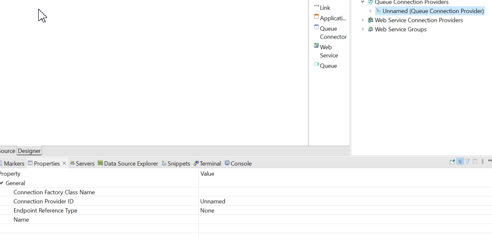
To write to the local database use the following values:
Property Value Connection Factory Class Name com.enactor.messageService.database.DatabaseMessageServiceConnectionFactory Connection Provider ID LocalJDBC Endpoint Reference Type Database Queue Endpoint Additional properties will appear when you change the Endpoint Reference Type, but you can leave all the other properties blank.
-
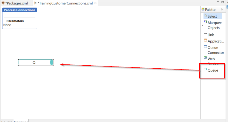
Now drag on a new queue:
-
Select the new queue, and in the property palette change its ID to
PosTransactionto match that in the standard diagram. Note that if your POS is a Master POS, you will need to override the MasterPosTransactions queue.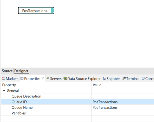
-
Now drag on a new Queue Connector:
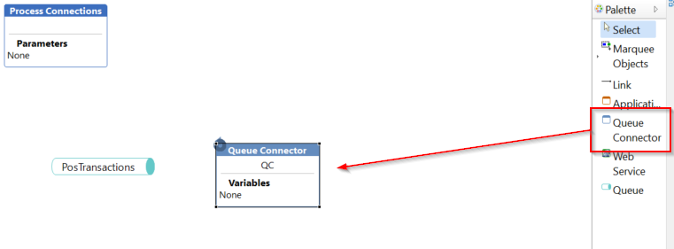
-
And then link the queue up to it using the
Linktool and then dragging from thePosTransactionsqueue to theQCQueue Connector: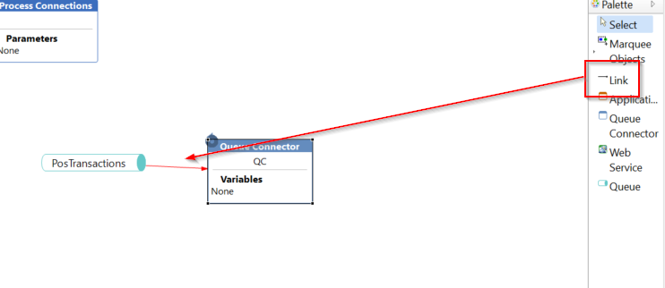
Note how the link is red, indicating that we haven't configured a
Provideron the link yet. -
To add a
Providerto thePosTransactionsqueue, open theOutlinein Eclipse and expand the until you see theOutbound Connectionssection in the PosTransactions queue: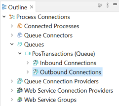
-
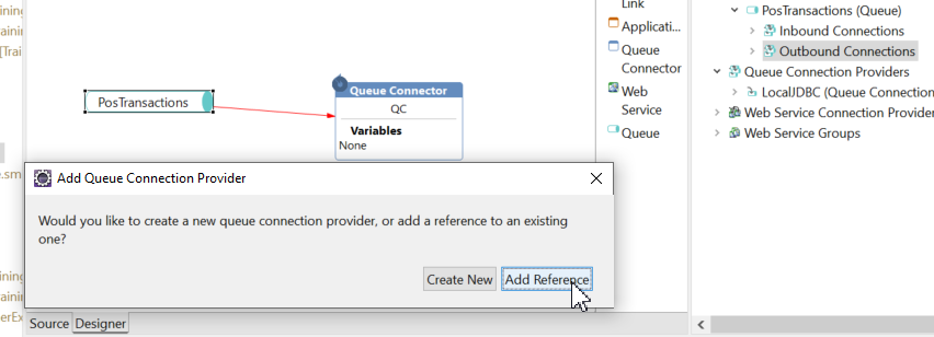
Right-Click on the
Outbound Connectionsand then selectAddfrom the context menu, and thenAdd Referencefrom the dialog that appears: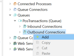
-
Select
LocalJDBCfrom the dialog and clickOK:
-
Now select the link you added to the diagram, and you can set the provider type to your new
LocalJDBCprovider: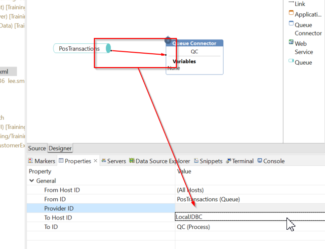
If you then deselect the link the diagram it should now turn grey
-
We can now add another queue to the right of the
Queue Connectorwhich will be where we write the transactions to. Drag on another Queue, and configure the Queue ID to beMyCustomQueue: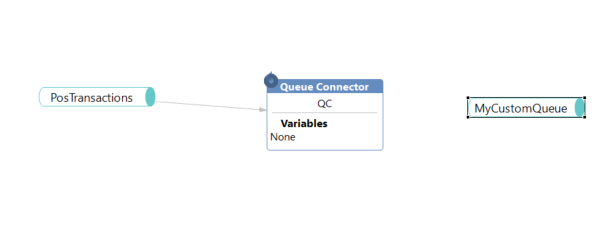
-
This time in the Outline view select the
MyCustomQueuequeue and right-click on theInbound Connectionselement. SelectAddand thenAdd Referenceand again chooseLocalJDBCfrom the dialog: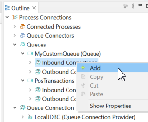
-
Then link the
QCQueue Connector up to your new custom queue: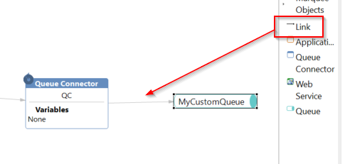
Note that the link didn't go red in this case. As we configured the provider before we created the link the Editor knew which provider to use and therefore automatically selected it for us.
If there were multiple providers available we would still have to select one
We have now completed the configuration of the connection diagram. To test this change, launch your POS making sure the project containing your new files is on the class path.
NOTE:
Make sure you are not running your POS with the-noDeployargument, otherwise the new Process Connection Diagram andProcessConnectionsTypeyou configured above will not be deployed to the database.
If you are running the Training Workspace, you can run the Training POS launch which will already have the correct setup.
Once the POS is ready, complete a sale as normal.
You can then use your database browser to examine the MessageQueue table and should see new entries in the MyCustomQueue database queue. Alternatively, look in the Estate Manager menu, Administration -> Message Service -> Queue Status and search for the new Queue Name, e.g. MyCustomQueue. The Total Size of that queue should go up for each message posted. Note that this total may also include system events as well as retail transactions.
Redirecting to a different queue
In the above example we added an additional queue as the target for transactions. In some situations it is more preferable to suppress the standard queues and only write to your custom queues. To do that you should instead override the Connected Process figures instead of just adding additional queues as shown in the next example.
The following example demonstrates this:
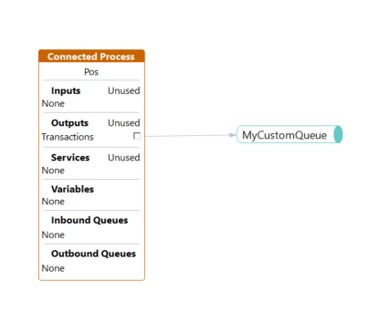
Here we have defined our own Connected Process with a Process ID that matches the standard diagram. We have then redeclared the Output and connected it directly up to our own queue.
Now when the POS sends a transactions it will only send it to our custom queue, and will not additionally write it to the standard PosTransactions queue.
Only the outputs that we have declared in this way are overridden - any other outputs which are present on the standard diagram are left unchanged.
Refer Connected Process for more info.